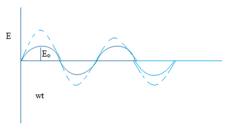
Alternating Current (AC Current)
If the magnitude of current changes with respect to distance and time sinusoidally then the current is called alternating current.
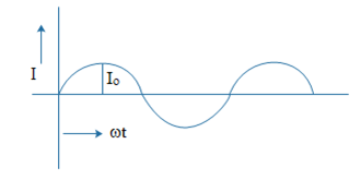
The equation of AC is written as:
I = Iosin[latex]\omega t[/latex] …………………. (1)
Where, Io is the peak value of alternating current (amplitude of current).
Here, [latex]\omega = \frac{2\pi}{T}[/latex]
Direct Current (DC Current)
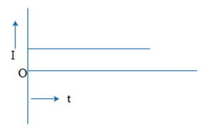
If the magnitude of current remains constant with respect to time and distance then the current is called direct current (DC Current).
Average value of alternating current / Mean value of alternating current (Im or Iav):
The average value of alternating current or mean value of alternating current is the DC current to send same amount of charge in the circuit in certain interval of time which is sent by alternating current in the same circuit in same time which is denoted by (Im or Iav).
We know that, the equation of alternating current is:
I = Iosin[latex]\omega t[/latex] ………………. (i)
Where, Io is the peak value of AC current, ‘[latex]\omega[/latex]’ is angular velocity which is equal to [latex]\frac{2\pi}{T}[/latex].
Let, small change dq is sent in the circuit in small time. So, we can write,
dq = Idt ……………. (ii)
Combining equations (i) and (ii),
dq = IoSin[latex]\omega t dt[/latex] ………………… (iii)
The total charge in either half cycle is obtained by integrating equation (iii) from 0 to T/2. i.e.
[latex]q = \int_{0}^{T/2}dq[/latex] ……………………… (iv)
Or, q = [latex]\int_{0}^{T/2}I_o sin\omega t dt[/latex]
Or, q = Io [latex]\int_{o}^{T/2}sin\omega t dt[/latex]
Or, q = Io [latex][\frac{-cos\omega t}{\omega}]_{0}^{T/2}[/latex]
Or, q = [latex]-\frac{I_o}{\omega}[cos\omega \frac{T}{2} – cos0][/latex]
Or, q = [latex]-\frac{I_oT}{2\pi}[cos\frac{2\pi}{T}\times \frac{T}{2} – cos0][/latex]
Or, q = [latex]-\frac{I_oT}{2\pi}[cos\pi – cos0][/latex]
Or, q = [latex]-\frac{I_oT}{2\pi}[-1-1][/latex]
Or, q = [latex]-\frac{I_oT}{2\pi}\times (-2)[/latex]
[latex]\therefore q = \frac{I_oT}{\pi}[/latex]
The average current of alternating current sends same amount of charge in time T/2.
So, we can write,
q = Iav [latex]\frac{T}{2}[/latex]
Or, [latex]\frac{I_oT}{\pi} = I_{av}\frac{T}{2}[/latex]
[latex]\therefore I_{av} = \frac{2I_o}{\pi} = I_o\times 0.637[/latex]
Similarly, in -ve half cycle, average current = [latex]I_o\times 0.637[/latex] and in one complete cycle it is 0.
Root mean square value of AC (Irms) (Virtual current or effective current):
The root mean square value of alternating current is the D.C. current to produce same amount of heat energy in the circuit of certain resistance which is produced by alternating current in the same circuit in same interval of time which is denoted by Irms.
The equation of alternating current is
I = Io [latex]sin\omega t[/latex] ……………. (i)
Where, Io = peak value of A.C., [latex]\omega = [/latex] angular velocity = [latex]\frac{2\pi}{T}[/latex].
Let, dH is the small amount of heat energy produced in the resistor in small time [latex]\Delta t[/latex]. So, we can write,
[latex]dH = I^2Rdt[/latex] ……………….. (ii)
Combining eqns. (i) and (ii),
[latex]dH = I_o^2sin^2\omega t Rdt[/latex]
Or, [latex]dH = I_o^2R sin^2 \omega t dt[/latex] …………….. (iii)
Now, the total heating energy produced in one complete cycle is obtained by integrating eqn. (iii) from 0 to T. Then, we get,
H = [latex]\int_{0}^{T} dH[/latex] ………… (iv)
Or, H = [latex]\int_{0}^{T} I_o^2 R sin^2 \omega t dt[/latex]
Or, H = Io2R[latex]\int_{0}^{T} sin^2\omega t dt[/latex]
Or, H = Io2R[latex]\int_{0}^{T}[\frac{1-cos2\omega t}{2}]dt[/latex]
Or, H = [latex]\frac{I_o^2R}{2}[\int_{0}^{T}dt – \int_{0}^{T} cos2\omega t dt][/latex]
Or, H = [latex]\frac{I_o^2 R}{2}[/latex]{[latex][t]_{0}^{T} – [\frac{sin2\omega t}{2\omega}]_{0}^{T}[/latex]}
Or, H = [latex]\frac{I_o^2R}{2}[/latex]{(T-0)-[latex](\frac{sin2\omega t – sin0}{2\omega})[/latex]}
Or, H = [latex]\frac{I_o^2R}{2}[/latex]{T-0}
[latex]\therefore H = \frac{I_o^2RT}{2}[/latex] …………………… (v)
Same amount of heat energy is produced in the circuit by root mean square value of alternating current in same interval of time of same resistance.
H = Irms2RT ………. (vi)
Combining eqns. (v) and (vi),
Irms2RT = [latex]\frac{I_oRT}{2}[/latex]
Or, Irms = [latex]\frac{I_o}{\sqrt{2}}[/latex]
Or, Irms = 0.70Io
This shows that Irms value of AC is almost 70% of peak value of alternating current.
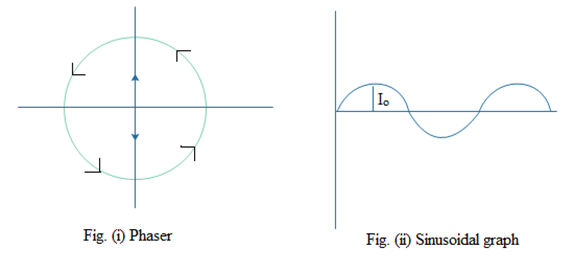
Phase/Phaser diagram:
The representation of alternating current and alternating source of emf in the circular diagram is called phaser diagram.
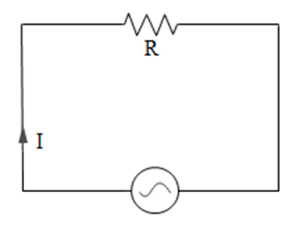
Alternating current (AC) through resistor
Let us consider, a circuit which contains alternating source of emf (E) and resistance (R), ‘I’ is the flow of alternating current in the circuit. We know that, the equation of alternating current, i.e.
E = EoSin[latex]\omega t[/latex] ………………. (i)
Where, Eo is the peak value of alternating source, [latex]\omega[/latex] is angular velocity.
The alternating source is drop across the resistance (R). So, we can write,
E = IR
Or, I = [latex]\frac{E}{R}[/latex] …………….. (ii)
Combining eqns. (i) and (ii),
I = [latex]\frac{E_o}{R}sin\omega t[/latex]
Where, [latex]\frac{E_o}{R}[/latex] is constant known as peak value of alternating current.
The phase diagram between alternating current and emf is given below:
Phaser diagram of alternating current and emf is:
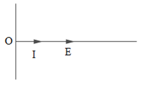
From eqns. (i) and (iii), we can see that alternating current and emf has no phase difference in purely resistive circuit.
Alternating Current (AC) through inductor
Let us consider, a circuit which contains alternating source of emf (E) and inductor of inductance (L). ‘I’ is the alternating current passing through inductor which is produced by alternating emf in the circuit.
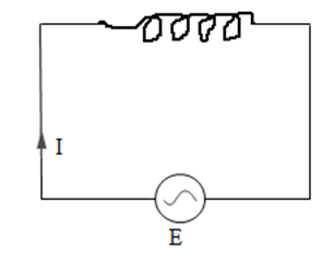
Now, the equation of emf of alternating source
E = Eosin[latex]\omega t[/latex] ………………. (i)
Where, Eo is the peak value of alternating source, ‘[latex]\omega[/latex]’ is the angular velocity.
The inductor develops the induced emf across it and in balance condition induced emf equal to emf of alternating source. So, we can write,
E = -[latex]\epsilon[/latex] …………… (ii)
We know that, the induced emf across the inductor is
[latex]\epsilon = -L\frac{dI}{dt}[/latex] …………………. (iii)
Combining eqns. (i), (ii) and (iii),
L[latex]\frac{dI}{dt} = E_o sin\omega t[/latex]
Or, dI = [latex]\frac{E_o}{L}sin\omega t dt[/latex] …………………. (iv)
Now, taking integration of equation (iv),
[latex]\int dI = \int \frac{E_o}{L}sin\omega t dt[/latex]
Or, I = [latex]\frac{E_o}{L}(-\frac{cos\omega t}{\omega})[/latex]
Or, I = [latex]\frac{E_o}{\omega L}(-cos\omega t)[/latex]
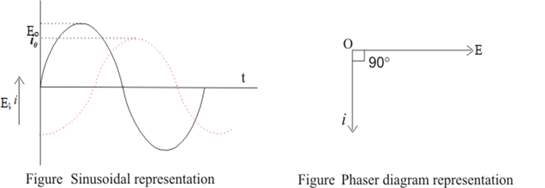
[latex]\therefore I = \frac{E_o}{\omega L}sin(\omega t -\frac{\pi}{2})[/latex]
[latex]I_o = \frac{E_o}{\omega L}[/latex] ………………… (v)
From ohm’s law,
I = V/R ………………….. (vi)
From eqns. (v) & (vi), ‘ ‘ must have the dimension of R, known as inductive resistance which is denoted by XL.
[latex]\therefore X_L = \omega L[/latex]
[latex]\therefore X_L = 2\pi fL[/latex]
DC current passes through inductor easily.
AC through Capacitor
Let us consider, a circuit which contains alternating source of emf ‘E’, and capacitor of capacitance ‘C’, ‘I’ is the flow of current in the circuit due to alternating source.
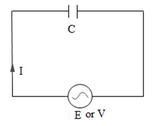
We know that, the equation of alternating source of emf is,
E = Eosin[latex]\omega t[/latex] …………………. (i)
Where, Eo is the peak value of alternating source, [latex]\omega[/latex] is the angular velocity.
Let, ‘V’ is the drop of voltage across the capacitor. So, we can write the following equation,
V = [latex]\frac{q}{C}[/latex]
Where, ‘q’ is charge stored in capacitor.
Or, q = VC ……………. (ii)
Here, V = E. So, we can write,
q = Eosin[latex]\omega[/latex].C
Or, q = cEo sin[latex]\omega t[/latex] ………….. (iii)
We know that, the relation between current and charge,
I = [latex]\frac{dq}{dt}[/latex] ………….. (iv)
I = [latex]\frac{d(CE_o sin\omega t)}{dt}[/latex]
Or, I = CEo [latex]\frac{dsin\omega t}{dt}[/latex]
Or, I = CEo [latex]\omega cos\omega t[/latex]
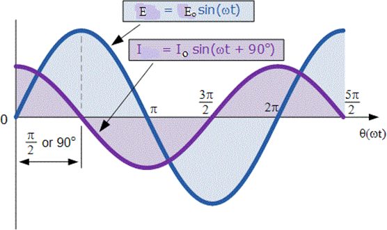
Or, I = (CEo [latex]\omega[/latex]) sin([latex]\omega t + \frac{\pi}{2}[/latex])
Or, I = Io [latex]sin(\omega t + \frac{\pi}{2})[/latex] ………………………. (v)
Where, Io is equal to CEo [latex]\omega[/latex]. i.e.
Io = CEo [latex]\omega[/latex]……………… (vi)
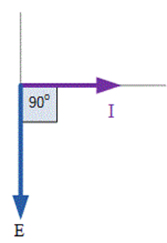
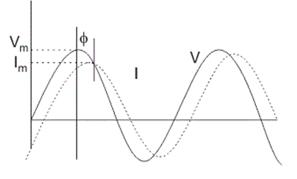
From eqn. (i) and (v), we can see that, current leads drop of voltage across the capacitor by [latex]\frac{\pi}{2}[/latex] or the drop of voltage across the capacitor lack current by [latex]\frac{\pi}{2}[/latex].
Now, the sinusoidal graph between current and drop voltage:
Phase diagram between current and drop of voltage:
From ohm’s law,
I = [latex]\frac{V}{R}[/latex] ………………….. (vii)
Re-arranging eqn. (vi),
Io = [latex]\frac{E_o}{(\frac{1}{\omega c})}[/latex] …………………….. (viii)
From eqns. (vii) and (viii),
[latex]\frac{1}{\omega c}[/latex] must have the dimension of R, known as capacitive resistance and denoted by XC.
So, Xc = [latex]\frac{1}{\omega C}[/latex]
XC = [latex]\frac{1}{2\pi fC}[/latex]
For DC Source, f = 0, and XC becomes which DC current is fully blocked-in capacitor.
Alternating Current through L-R Circuit
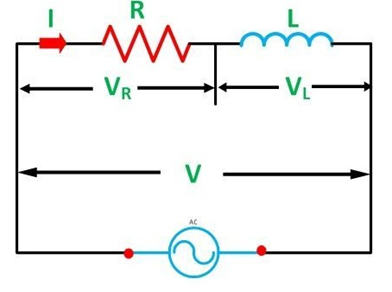
The equation of alternating source is:
E = EoSin[latex]\omega t[/latex]
Where, Eo is the peak value of alternating source, ‘[latex]\omega[/latex]’ is the angular velocity.
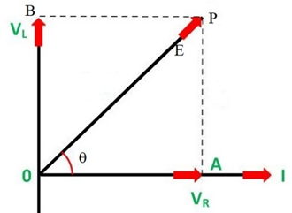
‘VR‘ and I are in same phase. ‘VL‘ leads current by [latex]\frac{\pi}{2}[/latex]. The phaser diagram between current ‘I’, ‘VL‘ and ‘VR‘ is given below:

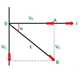
In figure, ‘E’ is the resultant voltage between ‘VR‘ and ‘VL‘. ‘[latex]\theta[/latex]’ is the angle between ‘E’ and ‘I’. From figure, we can write,
E = [latex]\sqrt{V_L^2 + V_R^2}[/latex] ………………….. (ii)
VL = IXL ………………….. (iii)
Where, ‘XL‘ is inductive reactance of inductor.
XL = [latex]\omega L[/latex]
XL = 2[latex]\pi fL[/latex]
Also, VR = IR ……………… (iv)
Combining eqns. (ii), (iii) and (iv),
E = [latex]\sqrt{I^2X_L^2 + I^2R^2}[/latex]
Or, E = I[latex]\sqrt{X_L^2 + R^2}[/latex]
Or, I = [latex]\frac{E}{\sqrt{X_L^2 + R^2}}[/latex] …………………… (v)
Where, [latex]\sqrt{X_L^2 + R^2}[/latex] acts as resistance in L-R circuit, known as impedance, which is denoted by ‘Z’.
[latex]\therefore Z = \sqrt{X_L^2 + R^2}[/latex]
Again, from figure, we can write,
tan[latex]\theta = \frac{V_L}{V_R}[/latex] …………… (vii)
Or, [latex]tan\theta = \frac{IX_L}{IR}[/latex]
[latex]\therefore \theta = Tan^{-1}(\frac{X_L}{R})[/latex] ……………………….. (viii)
Now, the sinusoidal equation of current is:
I = Iosin([latex]\omega t – \theta[/latex])
Alternating Current through C-R Circuit
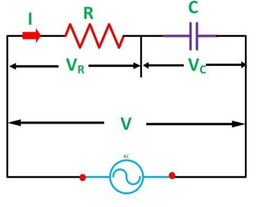
Let us consider, a circuit which contains alternating source of emf ‘E’, capacitor of capacitance ‘C’, resistor of resistance ‘R’. Capacitor and resistor are connected in series. So, same current I flow through them. ‘Vc‘ and ‘VR‘ are the drop of voltage across the capacitor and resistor respectively.
The equation of alternating source is:
E = Eosin[latex]\omega t[/latex]
Where, Eo is the peak value of alternating source, ‘[latex]\omega[/latex]’ is the angular velocity.
‘VR‘ and I are in same phase. ‘Vc‘ lacks current by [latex]\frac{\pi}{2}[/latex].
The phaser diagram between current ‘I’, ‘Vc‘ and ‘VR‘ is given alongside.

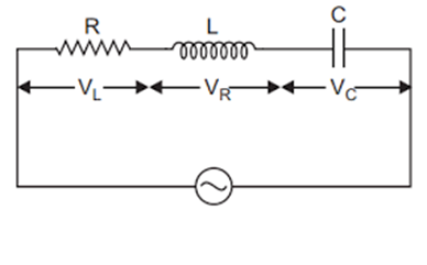
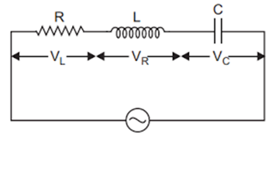
Alternating current through L-C-R circuit

Let us consider, a circuit which contains alternating source of emf ‘E’, inductor of inductance ‘L’, capacitor of capacitance ‘C’ and resistor of resistance ‘R’. Inductor, capacitor and resistor are connected in series. So that, ‘I’ be the flow of current through each of them. ‘VL‘, ‘Vc‘ and ‘VR‘ are the drop of voltage across inductor, capacitor and resistor respectively.
The equation of alternating source of emf is,
E = Eosin[latex]\omega t[/latex] ………………….. (1)
Where, ‘Eo‘ is the peak value of alternating source, ‘[latex]\omega[/latex]’ is the angular velocity.
The drop of voltage across the inductor i.e. ‘VL‘ leads current ‘I’ by [latex]\frac{\pi}{2}[/latex]. The drop of voltage across the capacitor i.e. ‘Vc‘ lacks current by [latex]\frac{\pi}{2}[/latex].
The drop of voltage across resistor i.e. ‘VR‘ is in same phase with ‘I’.
Now, phaser diagram between VL, Vc, VR and I is shown below:
‘VL‘ and ‘VC‘ are directed oppositely and suppose ‘VL‘ is greater than ‘VC‘. The resultant of ‘VL‘ and ‘VC‘ is (VL – VC) goes towards in the direction of ‘VL‘. ‘E’ is the resultant voltage between ‘VR‘ and (VL – VC). ‘[latex]\theta[/latex]’ is the phase angle between ‘E’ and ‘VR‘. In figure,
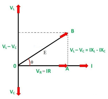
[latex]\Delta[/latex]OAB is right angled triangle.
So, we can write,
E2 = (VL – VC)2 + VR2
Or, E = [latex]\sqrt{(V_L – V_C)^2 + V_R^2}[/latex] …………………….. (2)
We know,
VL = IXL ……………. (3)
‘XL‘ is inductive reactance of inductor which is equal to
XL = [latex]\omega L[/latex]
XL = [latex]2\pi fL[/latex]
Also,
VC = IXC ………………… (4)
‘XC‘ is the capacitive reactance. i.e.
XC = [latex]\frac{1}{\omega C} = \frac{1}{2\pi fC}[/latex]
And, V = IR …………. (5)
Combining eqns. (2), (3), (4) and (5), then, eqn. (2) becomes,
E = [latex]\sqrt{(IX_L – IX_C)^2 + (IR)^2}[/latex]
Or, E = I[latex]\sqrt{(X_L – X_C)^2 + R^2}[/latex]
Or, I = [latex]\frac{E}{\sqrt{(X_L – X_C)^2 + R^2}}[/latex] …………………… (6)
Where, [latex]\sqrt{(X_L – X_C)^2 + R^2}[/latex] acts as resistance in LCR circuit known as impedance of LCR circuit, which is denoted by ‘Z’.
So, Z = [latex]\frac{(X_L – X_C)^2 + R^2}{}[/latex] ………………….. (7)
Again,
From triangle OAB,
Tan[latex]\theta = \frac{V_L – V_C}{V_R}[/latex] ………………… (8)
= [latex]\frac{IX_L – IX_C}{IR}[/latex]
= [latex]\frac{I(X_L – X_C)}{IR}[/latex]
Tan[latex]\theta = \frac{X_L – X_C}{R}[/latex]
[latex]\theta = tan^{-1}(\frac{X_L – X_C}{R})[/latex] ……………………. (9)
Eqn. (9) gives phase angle between E and I in LCR circuit.
Resonance of L-C-R circuit
Let us consider, a circuit contains alternating source of emf ‘E’, inductor of inductance ‘L’, capacitor of capacitance ‘C’ and resistor of resistance ‘R’ which are connected in series in the circuit.
Now, we know,
Total impedance of circuit (Z) for inductor dominated is given by,
Z = [latex]\sqrt{(X_L – X_C)^2+R^2}[/latex] …………………. (1)
Where, XL is inductive reactance which is equal to [latex]\omega L[/latex].
XL = [latex]\omega L[/latex]
Or, XL = [latex]2\pi fL[/latex] ……………. (2)
‘Xc‘ is the capacitive reactance.
Xc = [latex]\frac{1}{\omega C}[/latex]
Or, Xc = [latex]\frac{1}{2\pi fC}[/latex] ………………… (3)
The value of XL and Xc depends on frequency of AC source. At particular frequency (fo or fr) i.e. XL = Xc, then impedance becomes minimum and current becomes maximum known as resonance of L-C-R circuit. And corresponding frequency of A.C. is called resonant frequency.
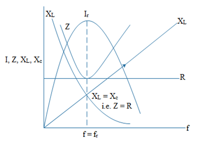
The above graph shows the relation between I, XL, Xc, Z with respect to frequency of AC source. When f = fo or fr, ‘I’ is maximum known as resonant current.
I = [latex]\frac{E}{\sqrt{(X_L – X_C)^2}+R^2}[/latex] …………………. (4)
When f = fo, then, XL = XC
Ir = [latex]\frac{E}{R}[/latex] …………………. (4)
Now resonant frequency
XL = XC …………………… (6)
[latex]2\pi f_rL = \frac{1}{2\pi f_r C}[/latex]
Or, fr2 = [latex]\frac{1}{4\pi^2LC}[/latex]
Or, fr = [latex]\frac{1}{2\pi \sqrt{LC}}[/latex] ………………. (7)
Equation (7) gives resonant frequency in LCR circuit. This shows that resonant frequency depends on inductance and capacitance but not resistance.
Q – Factor
Q-factor is the characteristics of resonating circuit and resonance of LCR circuit. It is defined as the ratio of drop of voltage across the capacitor or inductor to the drop of voltage in resistance in resonating LCR circuit. i.e. Q-factor = [latex]\frac{V_L}{V_R}[/latex] ……………….. (1)
= [latex]\frac{IX_L}{IR}[/latex]
= [latex]\frac{X_L}{R}[/latex]
= [latex]\frac{2\pi f_rL}{R}[/latex] …………………….. (2)
Again, we know,
fr = [latex]\frac{1}{2\pi}\sqrt{\frac{1}{LC}}[/latex] …………………… (3)
combining eqns. (2) and (3),
Q-factor = [latex]\frac{2\pi}{2\pi}\sqrt{\frac{1}{LC}}\times L \times \frac{1}{R}[/latex]
Q-factor = [latex]\frac{1}{\sqrt{LC}}\times \frac{1}{R}[/latex]
= [latex]\frac{1}{R}\sqrt{\frac{L^2}{LC}}[/latex]
Q-factor = [latex]\frac{1}{R}\sqrt{\frac{L}{C}}[/latex] ………………… (4)
Also, for capacitor,
[latex]\frac{V_C}{V_R} = \frac{IX_C}{IR}[/latex]
= [latex]\frac{1}{\omega_c R}[/latex]
= [latex]\frac{1}{2\pi f_rCR}[/latex]
= [latex]\frac{2\pi \sqrt{LC}}{2\pi CR}[/latex]
= [latex]\frac{1}{R}\sqrt{\frac{LC}{C^2}}[/latex]
= [latex]\frac{1}{R}\sqrt{\frac{L}{C}}[/latex]
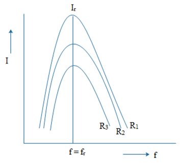
Equation (4) gives the Q-factor of LCR resonating circuit. Lower the resistance, higher the Q-factor. Low resistance in LCR resonating circuit gives sharp and high value of current or frequency.
Power consumed in LCR circuit
Let us consider, a circuit which contains alternating source of emf ‘E’, inductor of inductance ‘L’, capacitor of capacitance ‘C’, resistor of resistance ‘R’, which are connected in series in the circuit. ‘I’ is the flow of current in the circuit.
We know that,
Emf of alternating source is:
E = Eosin[latex]\omega t[/latex] ………………… (1)
Where, Eo = Peak value of alternating emf, [latex]\omega =[/latex] Angular velocity = [latex]\frac{2\pi}{T}[/latex]
The small work done in circuit is written as,
dw = Pdt ……………… (2)
We know that,
P = IE
So, dw = IEdt …………….. (3)
For inductor dominating LCR circuit, the eqn. of current is written as:
I = Iosin[latex](\omega t – \theta)[/latex] …………….. (4)
Where, [latex]\theta[/latex] is the phase angle between ‘E’ and ‘I’ in the circuit.
Combining eqns. (1), (3) and (4),
dw = Io [latex]sin(\omega t – \theta)E_o sin\omega t dt[/latex]
Or, dw = IoEosin[latex](\omega t – \theta)sin\omega t dt[/latex]
Or, dw = IoEo(sin[latex]\omega t cos\theta – cos\omega t.sin\theta).sin\omega t dt[/latex]
Or, dw = IoEo [latex](sin^2\omega t cos\theta – sin\omega t.cos\omega t.sin\theta)dt[/latex]
Or, dw = IoEo {[latex](\frac{1-2cos2\omega t}{2})cos\theta – (\frac{sin2\omega t}{2})sin\theta[/latex]}dt
Or, dw = IoEo {[latex]\frac{1}{2}(dtcos\theta – cos2\omega t cos\theta dt) – (\frac{sin2\omega t sin\theta dt}{2})[/latex]} ………………….. (5)
The total workdone in one complete cycle is obtained by integrating equation (5) from 0 to T. So, we can write,
W = [latex]\int_{0}^{T}dw[/latex] ………………. (6)
Or, W = [latex]\frac{I_oE_o}{2}[/latex]{[latex]\int_{0}^{T} dtcos\theta – \int_{0}^{T}cos2\omega t cos\theta dt – \int_{0}^{T} sin2\omega t sin\theta dt[/latex]} ………….. (7)
Where, [latex]\int_{0}^{T}cos2\omega tdt = 0[/latex]
and, [latex]\int_{0}^{T}sin2\omega tdt = 0[/latex]
So, W = [latex]\frac{I_oE_o}{2}{[t]_{0}^{T}cos\theta}[/latex]
= [latex]\frac{I_oE_o}{2}[T – 0]cos\theta[/latex]
= [latex]\frac{I_oE_oTcos\theta}{2}[/latex] ………………… (8)
We know,
P = [latex]\frac{W}{T}[/latex] …………………………. (9)
Or, P = [latex]\frac{I_oE_ocos\theta T}{2T}[/latex]
Or, P = [latex]\frac{I_oE_ocos\theta}{2}[/latex]
Or, P = [latex]\frac{I_o}{\sqrt{2}}.\frac{E_o}{\sqrt{2}}.cos\theta[/latex]
Or, P = Irms Erms [latex]cos\theta[/latex] ……………………….. (10)
Or, P = Pvcos[latex]\theta[/latex]
Or, Cos[latex]\theta = \frac{P}{P_v}[/latex] , where, Pv is virtual power, cos[latex]\theta[/latex] = Power factor.
Power factor is defined as the ratio of true power to virtual power.
Power factor of different circuit
1. For purely resistive circuit, [latex]\theta = 0^o[/latex]
cos[latex]\theta = cos0 = 1[/latex]
Power factor = [latex]\frac{P}{P_v} = 1[/latex]
[latex]\therefore P = P_v[/latex]
2. For purely capacitive circuit, [latex]\theta = 90^o[/latex]
Cos90 = 0
[latex]\therefore[/latex] Power factor = 0
3. For purely inductive circuit, [latex]\theta = 90^o[/latex]
Cos[latex]\theta = cos90 = 0[/latex]
[latex]\therefore[/latex] Power factor = 0
4. For C-R circuit:
cos[latex]\theta = \frac{V_R}{E}[/latex]
= [latex]\frac{IR}{IZ}[/latex]
= [latex]\frac{R}{\sqrt{X_C^2 + R^2}}[/latex]
= [latex]\frac{R}{\sqrt{(\frac{1}{2\pi fC})^2 + R^2}}[/latex]
5. For LR circuit:
cos[latex]\theta = \frac{V_R}{E}[/latex]
= [latex]\frac{IR}{IZ}[/latex]
= [latex]\frac{R}{\sqrt{X_L^2 + R^2}}[/latex]
= [latex]\frac{R}{\sqrt{(2\pi fL)^2 + R^2}}[/latex]
6. For LCR circuit:
Inductor dominated:
cos[latex]\theta = \frac{R}{\sqrt{(X_L – X_C)^2 + R^2}}[/latex]
Capacitor dominated:
[latex]cos\theta = \frac{R}{\sqrt{(X_C – X_L)^2 + R^2}}[/latex]